
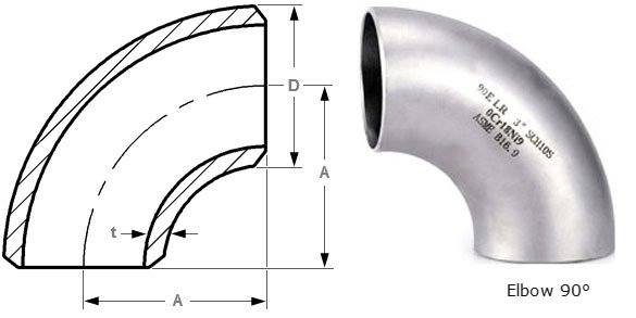
| NPS | Outside Diameter (D) (mm) | 90° Long Radius Center-to-End (A) (mm) | 90° 3D Center-to-End (A) (mm) |
|---|---|---|---|
| ½″ | 21.3 | 38 | – |
| ¾″ | 26.7 | 38 | 57 |
| 1″ | 33.4 | 38 | 76 |
| 1¼″ | 42.2 | 48 | 95 |
| 1½″ | 48.3 | 57 | 114 |
| 2″ | 60.3 | 76 | 152 |
| 2½″ | 73.0 | 95 | 190 |
| 3″ | 88.9 | 114 | 229 |
| 3½″ | 101.6 | 133 | 267 |
| 4″ | 114.3 | 152 | 305 |
| 5″ | 141.3 | 190 | 381 |
| 6″ | 168.3 | 229 | 457 |
| 8″ | 219.1 | 305 | 610 |
| 10″ | 273.0 | 381 | 762 |
| 12″ | 323.8 | 457 | 914 |
| 14″ | 355.6 | 533 | 1067 |
| 16″ | 406.4 | 610 | 1219 |
| 18″ | 457.0 | 686 | 1372 |
| 20″ | 508.0 | 762 | 1524 |
| 22″ | 559.0 | 838 | 1676 |
| 24″ | 610.0 | 914 | 1829 |
| 26″ | 660.0 | 991 | 1981 |
| 28″ | 711.0 | 1067 | 2134 |
| 30″ | 762.0 | 1143 | 2286 |
| 32″ | 813.0 | 1219 | 2438 |
| 34″ | 864.0 | 1295 | 2591 |
| 36″ | 914.0 | 1372 | 2743 |
| 38″ | 965.0 | 1448 | 2896 |
| 40″ | 1016.0 | 1524 | 3048 |
| 42″ | 1067.0 | 1600 | 3200 |
| 44″ | 1118.0 | 1676 | 3353 |
| 46″ | 1168.0 | 1753 | 3505 |
| 48″ | 1219.0 | 1829 | 3658 |
Each flange follows a rigorous 8-step forging and quality-control process to ensure conformance with ASTM A182 and ASME standards.
Prime 304 stainless steel billet sourced and certified.
Heat to 1100°C – 1250°C for optimal forgeability.
Shape billet into flange geometry under controlled pressure.
Solution anneal at 1040°C – 1120°C, then quench.
CNC machining, drilling, and surface finishing.
Tensile, hardness, PMI, visual and impact tests performed.